
This is solution 1
Introduction
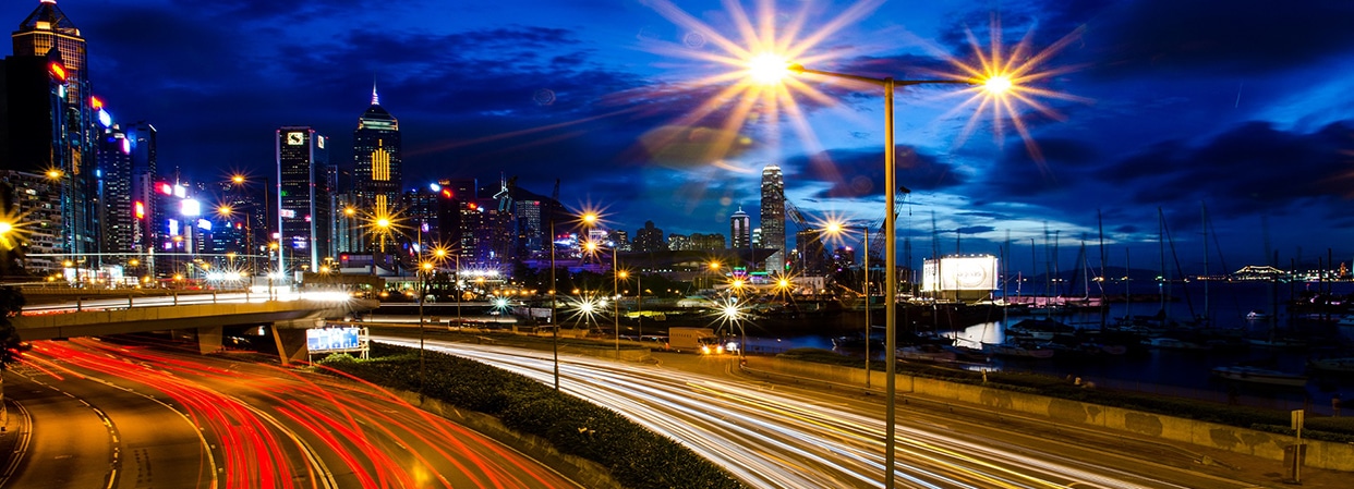
The main function of road lighting is to provide the necessary visual conditions for road users to travel safely and comfortably at night. Road lighting should reveal all features of roads and traffic (including sidewalks, lanes, road signs, road markings, curbs, verges, zebra crossings, crosswalks, etc.) that are important to all users including pedestrians, cyclists and drivers very important. Moreover, street lighting fixtures, in addition to being efficient, reliable and durable, should also look good day and night and be in harmony with the surrounding environment.
A general approach to road lighting design is based on the concept of luminance, the aim of which is to provide a bright pavement background against which the outlines of objects can be seen. Therefore, road lighting design generally uses brightness level, road surface brightness uniformity and glare control as the main indicators. However, when it comes to closer vision tasks, such as in conflict areas including parking lots, bus terminals, and bicycle lanes, we cannot provide a bright background so that the outline of the object is displayed then direct light is needed to exposed object. Likewise, in areas of heavy traffic, such as tollbooths and transit interchanges, much of the view of the road surface may have been obscured by vehicles, thus it can not provide background for displaying objects. In both cases, the illuminance method will be more appropriate. Nonetheless, road lighting levels (lighting level and uniformity) and appropriate glare control are widely used in all international recommendations for motorized traffic.
Lighting design standards
Roadway lighting levels are described in classes with different lighting parameters to suit local lighting requirements. These classes should be selected according to the function of the road, traffic density, traffic complexity, traffic segregation, pedestrian flow and ambient brightness. For road classification, you can refer to EN13201 standard.
Carriageways(M1 to M6)
For motor vehicle lanes, there are 5 lighting levels (M1, M2, M3, M4 and M5), and the 5 lighting levels are shown in the table below for different types of roadway lighting. The recommended maintained average luminance (Lav) ensures that the roadway is bright enough to adequately display objects, while the recommended overall uniformity ratio (Uo), the ratio of minimum to average luminance over a defined area, ensures that no part of the road surface is too dark So that it cannot be used as a background for displaying objects. The recommended longitudinal uniformity ratio (Ul) is the ratio of the minimum luminance to the maximum luminance along a longitudinal line passing through the observer’s position, ensuring that visible visual spots are avoided on illuminated road surfaces. Disabling glare, measured as Threshold Increment (TI), reduces the contrast between an object and its background. The recommended TI limit ensures that glare does not impair the vision of road users.
| Lighting class | Dry | Wet | TI in % | SR | ||
| Lav in cd/m2 | Uo | UI | Uo | |||
| M1 | 2.0 | 0.40 | 0.70 | 0.15 | 10 | 0.5 |
| M2 | 1.5 | 0.40 | 0.70 | 0.15 | 10 | 0.5 |
| M3 | 1.0 | 0.40 | 0.60 | 0.15 | 10 | 0.5 |
| M4 | 0.75 | 0.40 | 0.60 | 0.15 | 15 | 0.5 |
| M5 | 0.50 | 0.35 | 0.40 | 0.15 | 15 | 0.5 |
| M6 | 0.30 | 0.35 | 0.40 | 0.15 | 20 | 0.5 |
Conflict Areas(C1 to C5)
It is common for driveways to adjoin or lead to public utility areas such as bus terminals, ferry terminals, taxi ranks, toll booths or car parks. Other similar areas of interest include intersections, pedestrian crossings, and roundabouts. These are often referred to as “conflict areas” where it is more appropriate for lighting design to use the illuminance approach.
Area lighting technology is used to illuminate open spaces such as conflict areas where there is mixed traffic or where traffic merges and diverges. The main requirements are to provide specific illuminance levels and uniformity ratios, and to adequately control glare. In conflict areas, vision tasks are often more difficult than on straight roads due to changes in road layout or heavy patronage by pedestrians, cyclists, or other road users. For these areas (including junctions, roundabouts, pedestrian crossings), higher lighting levels should be provided, as described below.
| Class | Horizontal illuminance | ||
| Eav[minimum maintained] (lux) | Uo[minimum] | Threshold increment(TI in %) | |
| C0 | 50 | 0.4 | 15 |
| C1 | 30 | 0.4 | 15 |
| C2 | 20 | 0.4 | 15 |
| C3 | 15 | 0.4 | 20 |
| C4 | 10 | 0.4 | 20 |
| C5 | 7.5 | 0.4 | 20 |
Footpaths and Cycle Tracks (without motorized traffic, P1 to P6)
There are 5 lighting levels for sidewalks and bicycle lanes without motorized lanes. Unlike motorway users, pedestrians prefer brightly lit environments for a sense of safety. Therefore, the lighting of such areas is mainly based on the illuminance level, as shown in the table below. For areas (alleys) that require face recognition, lamps with a color rendering index greater than 70 or higher should be selected, and there are also requirements for the minimum vertical illuminance level to enhance the sense of security and prevent crime.
| Lighting class | Average horizontal illuminance Eav in lx | Minimum horizontal illuminance Emin in lx | Ti in % | Additional requirement if facial recognition is necessary | |
| Minimum vertical illuminance Ev,min in lx | Minimum semi- cylindrical illuminance Esc,min in lx | ||||
| P1 | 15 | 3.0 | 20 | 5.0 | 3.0 |
| P2 | 10 | 2.0 | 25 | 3.0 | 2.0 |
| P3 | 7.5 | 1.5 | 25 | 2.5 | 1.5 |
| P4 | 5.0 | 1.0 | 30 | 1.5 | 1.0 |
| P5 | 3.0 | 0.6 | 30 | 1.0 | 0.6 |
| P6 | 2.0 | 0.4 | 35 | 0.6 | 0.4 |
Design layout of road lighting simulation
The layout of street lighting includes two parts. One is the street profile and another part is pole arrangement. Street Profiles to define the configuration of your street. And pole arrangement is about how the street light poles are sitting on the street.
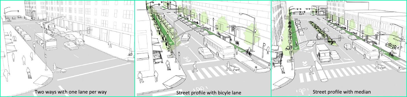
Definition of a street profile
Street profile is mainly refers to what is road composed of? In different countries or cities, there are many different street profiles. owever, it mainly includes components covering motor vehicle lanes, bicycle lanes, sidewalks, parking lanes, grass strip, median and emergency lanes, etc. Urban roads are often a combination of these. Sometimes it only has motor vehicle lanes, sometimes it is a combination of motor vehicle lanes and bicycle lanes, or it is a combination of motor vehicle lanes and isolation islands plus emergency lanes, etc. We list different street profiles as follows.
Pole arrangments
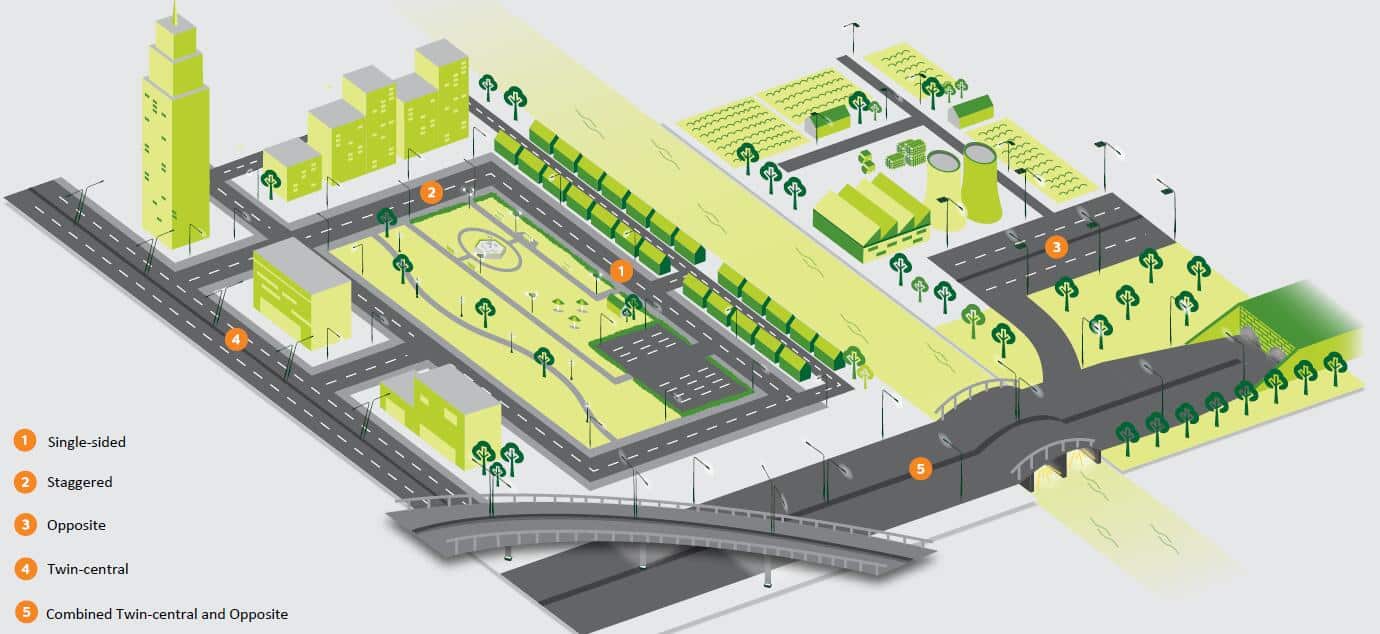
After the lighting standard and street profiles are confirmed, the arrangement of poles should also be selected according to the road conditions. In addition, the distance between light poles, height of light poles, Boom angle, setback, overlang, and boom length must be confirmed before implementing lighting simulation. Due to space limitations, we will not introduce too much here. If you are interested, you can refer to our other blog regarding luminaire arrangement. The following are five common pole arrangements of street lighting.
Single-sided
Single-sided arrangement is adopted when the width of the road does not exceed the installation height of the lamps. Street light fixture of this type arrangement of is located on the side of the road. The advantage of this arrangement is to provide the driver with good visual guidance of the road and good longitudinal uniformity. A major disadvantage of this type of distribution is that the brightness of the far-side road surface must be lower than that of the near-side road surface of the lamp, but the overall uniformity can generally be well improved through reasonable lighting distribution design. Furthermore, this arrangement is also recommended for bypass road.
Staggered
Staggered arrangement is mainly adopted when the width of the road is between 1 and 1.5 times the installation height of the lamps. Luminaires of this type arrangement are located on both sides of the road in a staggered or zigzag pattern. Alternating bright and dark flakes can create an unpleasant zigzag effect, so we should pay attention to the uniformity of the brightness of the road surface. Staggered arrangement is generally not recommended for highways because it is difficult to achieve acceptable longitudinal uniformity.
Opposite
Opposite arrangement is mainly used when the width of the road is greater than 1.5 times the installation height of the street lamps. The luminaires in this arrangement face each other. It is recommended to use on wide carriageways or highways.
Twin-central
Twin-central arrangement is mainly used for dual carriageways. Lighting columns are located in the central reservation. Each lighting post typically has two light fixtures mounted back-to-back on each side of the driveway. This type of lighting arrangement often requires roads to be provided with wide islands, which reduces capital and maintenance costs. For this lighting arrangement, we need to pay attention to the potential risks during lighting maintenance because the isolation island is close to the fast lane. So it is recommended to do it in the case of closed lanes.
Combined Twin-central and Opposite
In combined twin-central and opposite arrangement, twin luminaires located on the central reservation are combined with the opposite arrangement. Normally the hard shoulder is set on the expressway, and the lighting column should be set on the side of the hard shoulder. In other words, opposite arrangement is preferred when compared to twin-central arrangement in such road layout. This type of arrangement is recommended for expressways with exceptionally wide carriageways.
DIALux design for road lighting simulation
After the lighting standard, street profile and pole arrangement are confirmed, we need the help of lighting software. The street profile which we mentioned now can be imported into DIALux, including the number of motor vehicle lanes, sidewalks (bicycle lanes), median, etc. Then we can import luminaire IES files, and an experienced designers can quickly select the appropriate street lamp, wattage and spectrum according to the above information. Then adjust the design as per requirement.
Basic steps of road lighting simulation by Dialux
- Identify the lighting standard (requirement)
- Create street profiles
- Select the street lighting equipment
- Adjust the street light arrangement (proper placement of pole and light)
- Calculate the lighting parameters and adjust the design as required
- Export DIALux lighting design report
Different street profiles in one project
Streets are the lifeblood of neighborhoods and the foundation of our urban economy. They account for more than 80 percent of all public spaces in cities, have the potential to facilitate commercial activity, serve as front yards for residents, and provide a safe place for people to move around either by walking, bicycle, car, or other transportation.
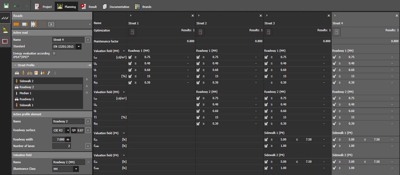
The composition of roads includes motor vehicle lanes, bicycle lanes, sidewalks, parking lanes, grass strips, medians and emergency lanes, etc. So there will be more than one street profile in one project. The street profiles has been clearly defined at the beginning of the lighting design, and we need to import these profiles into the lighting simulation software during street lighting design. In the picture below, we have imported several common street profiles into DIALux. Through lighting simulation, we can choose suitable lamps(wattage, lens, installation method, etc.) for different street profiles in the project.
Comparison of variants
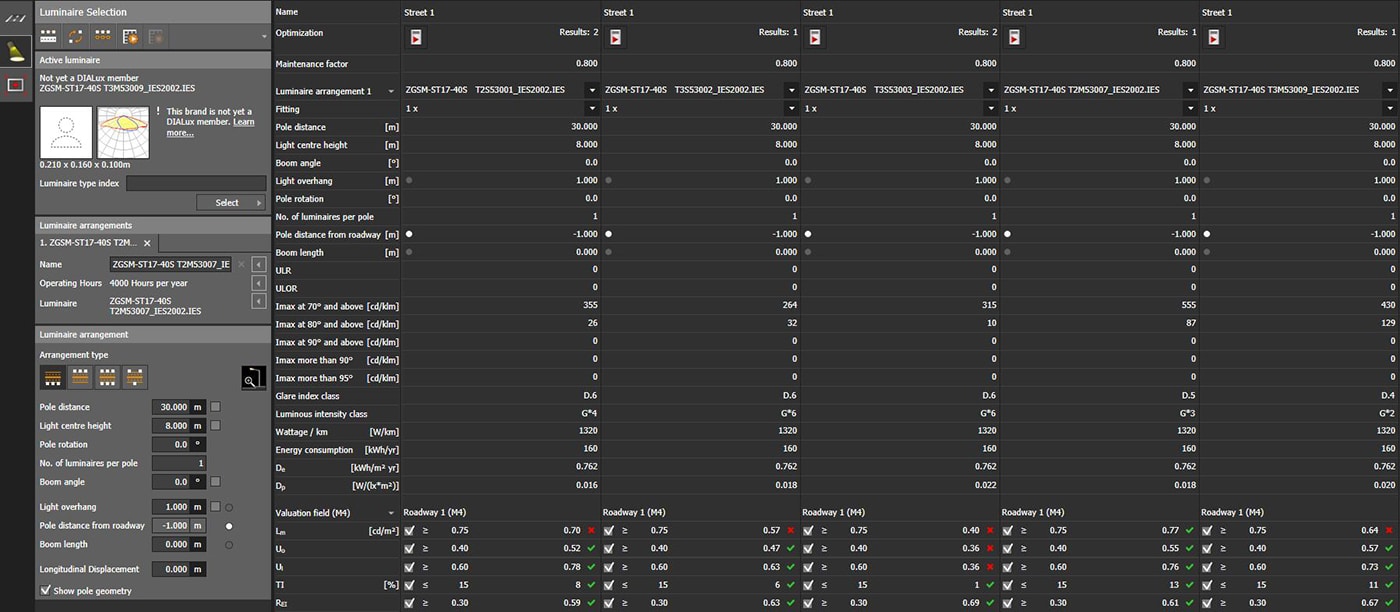
After the street plan is confirmed, we need to determine the appropriate lighting fixtures for the street plan. The general wattage can be determined by Wattage/Km (generally 1.2-1.5KW/Km when the road width is 7m, and M4 lighting standard is required). For example, when the distance between the light poles is 30mand the lights are placed on one side. The suitable wattage is 40W-50W. Then we can choose the 40W ZGSM Rifle street light. Here comes the question, what kind of lens is suitable? For DIALux, We can import different lenses into the software, and the result is clear at a glance in the below picture. T2M53007 is the most suitable for this road condition, then we move to continuously optimize other parameters. Of course, this method can also be used to determine the wattage and type of street lamps.
Automatic optimization of luminaire arrangement
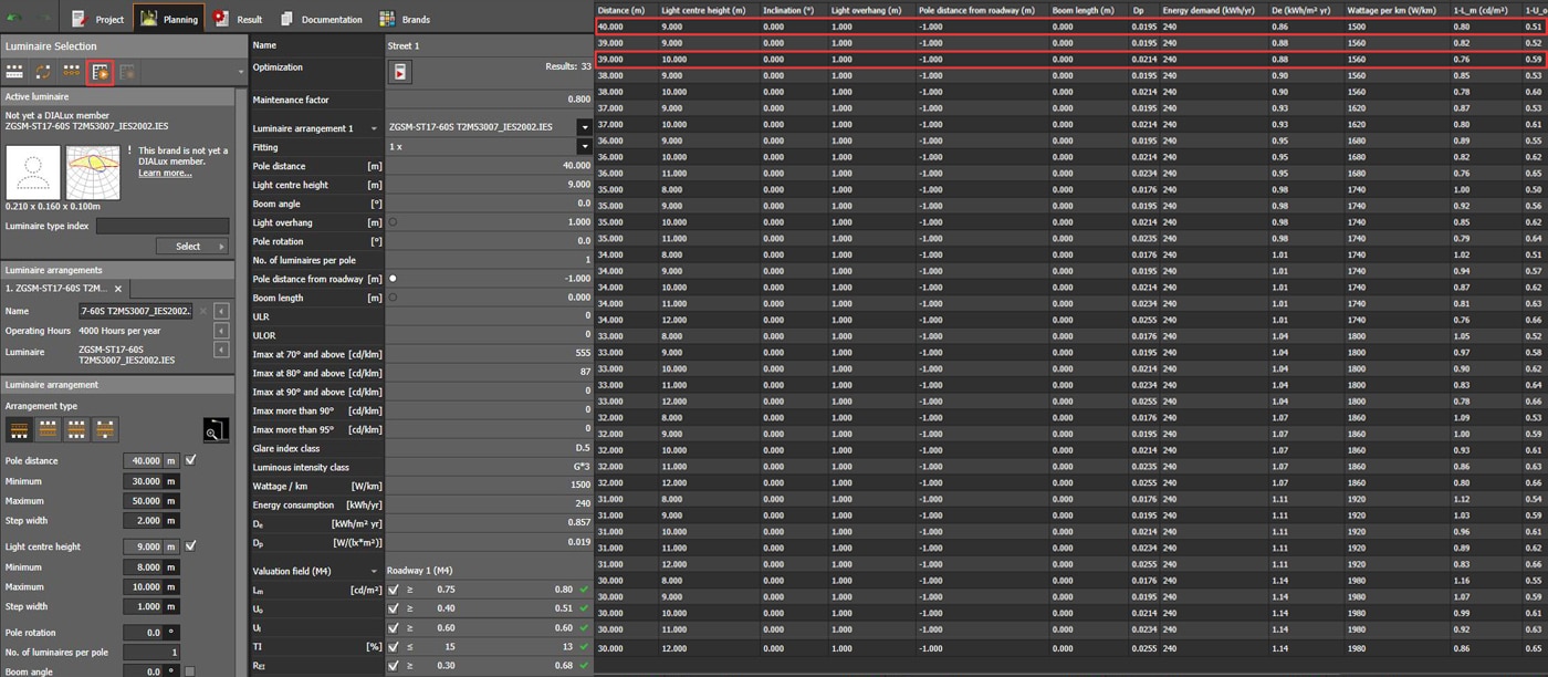
Generally speaking, the distance between light poles, height of light poles, Boom angle, setback, overlang, and boom length are all confirmed. If you are interested in the meaning of each parameter, please refer to our other article. But some projects require us to suggest the appropriate light pole spacing, light pole height and boom, etc. At this time, lighting simulation can play its role to check the suitable parameters and DIALux EVO has great advantages in this aspect. By checking the parameters that need to be optimized, we can get the desired results. These results can provide a reference for the customer’s project planning. The lighting design scheme selected in this way is often better, which can avoid too small light pole spacing, unreasonable boom length, unreasonable inclination angle, etc. Because these often cause waste of resources, unreasonable lighting, and even light pollution. The figure below shows how DIALux EVO can achieve automatic optimization of a street light arrangement. As we can see, the suitable pole height is 9m or 10m, while the pole space can reach 40 meters after optimization.
ZGSM street lighting solution
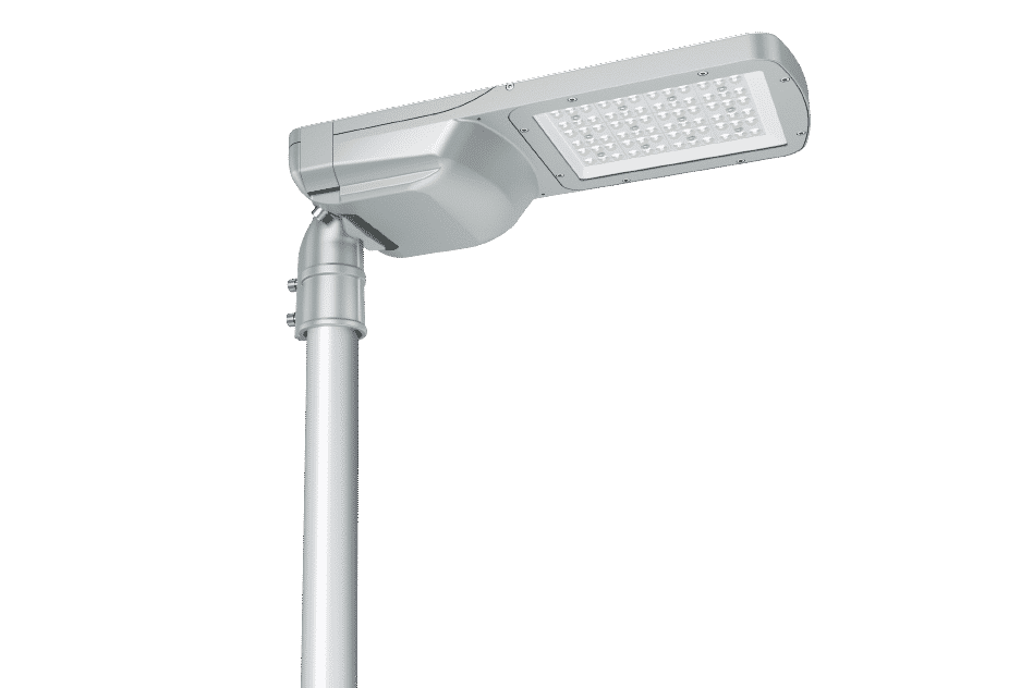
Rilfe series street light LED
| Performance summary of Rilfe series |
| Initial Lumens: Up to 38400 lumens |
| Input Power: Up to 240W |
| Efficiency: 140-170lm/W |
| CCT: 2700K, 3000K, 4000K, 5000K, 5700K |
| Main features: Tool-free open |
| Ceritificate: ENEC, ENEC+, CE, RoHS, CB, LM79, 62722, 62717, etc |
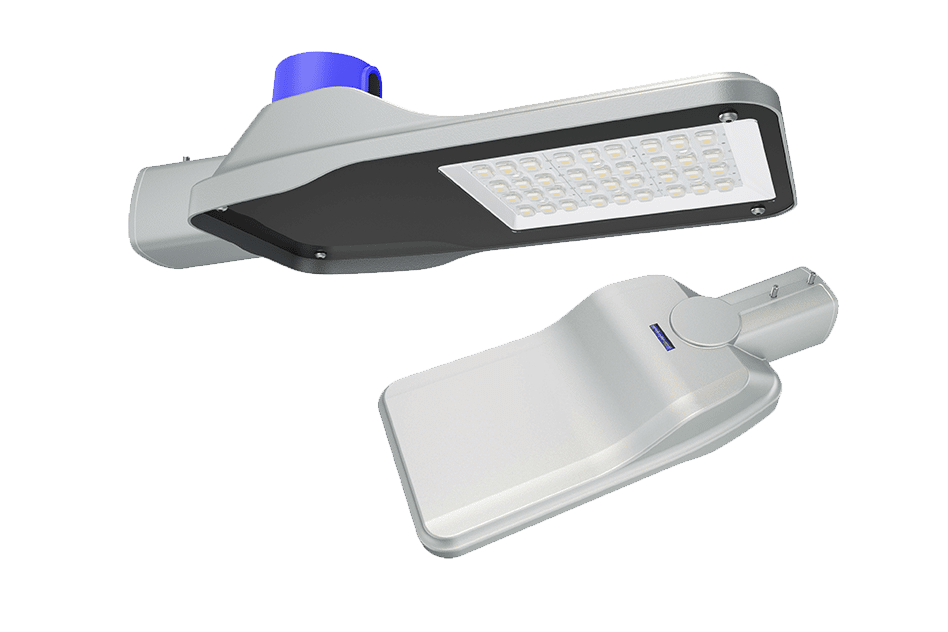
Nova series street light
| Performance summary of Nova series |
| Initial Lumens: Up to 21000 lumens |
| Input Power: Up to 150W |
| Efficiency: 120-140lm/W |
| CCT: 2700K, 3000K, 4000K, 5000K, 5700K |
| Main features: Competitive price |
| Ceritificate: CE, RoHS, LM79, ISTMT |
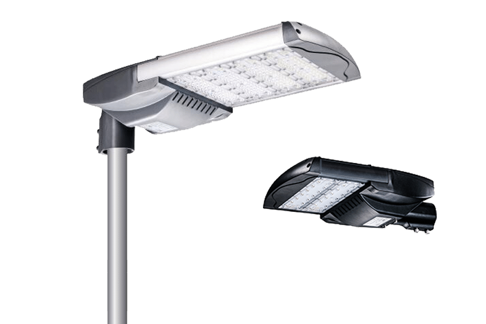
H series street light
| Performance summary of H series |
| Initial Lumens: Up to 38400 lumens |
| Input Power: Up to 240W, 300W customized |
| Efficiency: 125-165lm/W |
| CCT: 2700K, 3000K, 4000K, 5000K, 5700K |
| Main features: Moular design |
| Ceritificate: ENEC, UL, CE, CB, RoHS, LM79, ISTMT |
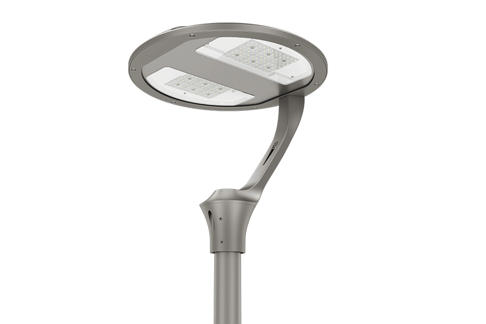
Halo post top street light
| Performance summary of Halo series |
| Initial Lumens: Up to 21750 lumens |
| Input Power: Up to 150W |
| Efficiency: 135-150lm/W |
| CCT: 2700K, 3000K, 4000K, 5000K, 5700K |
| Main features: 6 ways of installation |
| Ceritificate: ENEC, CE, CB, RoHS, LM79, ISTMT |
Summary
Through this article, we hope that everyone has a certain understanding of road lighting simulation and the application of DIALux EVO in lighting simulation. In fact, lighting simulation is very complicated. If you are interested, you can read it together with our other two articles. One of them is an introduction to some key factors that need to be paid attention to in road lighting simulation, and the other is about the arrangement of street lamps. This article focuses on some applications of DIALux EVO in road lighting simulation. If you want to know more about the application of DIALux EVO, you can check the tutorial on DIALux EVO official website, which is relatively detailed but charged. In addition, if you are still choosing street lights suitable for your project, you can check our lighting fixture catalog such as the above ZGSM street light solutions. Finally, everyone is welcome to communicate with each other and increase the knowledge of road lighting design and product selection. We offer customer service 24/7!


